
PLEASE READ CAREFULLY:
It is essential you read this document and book in for a calibration of your TCU with one of our authorized reps.
There is many ways the engines are tuned, some even terribly, we have seen engine computers sending 100nm+ on idle to the TCU.
And on the polar opposite: a chip doesn’t make full use of the torque system and almost guarantees a stock gearbox will slip with enough power without a flash of the engine ECU. (The transmitted torque is usually below stock even though engine output has increased in most cases)
All TCU’s are sent with a firm base map to ensure no slip (No matter the tuning style), this doesn’t suit many vehicles but it ensures no slippage in case someone drives without booking in a session or reading this document. – DO NOT DRIVE THE VEHICLE WITHOUT READING THIS DOCUMENT IN FULL!
Please ensure we scale your ACTUAL engine torque to the TCU for smooth operation. This is best done in person, or thru a hot-spot to your phone (with your own laptop connected to the car) – If we cannot complete your booking for any reason, it is your responsibility to request another booking when possible to complete the tuning process and remember, until we say its OK its not OK until then! We will let you know when we are satisfied with the tuning.
A tuning session is only completed when we say so! A bit of patience goes a long way, removing the kit while the tuning has not yet been completed is the recommended procedure in any case. This kit is used entirely at your own risk and any assumption things are working correctly is entirely your responsibility. When we are satisfied, we will let you know.
Any vehicle producing over 700nm at the rear tyres needs special care, it is recommended you ask for global torque limiters in 1st,2nd,5th and 6th gears to prolong your transmissions health.
Usability notes:
There is ZERO lock up in 1st gear and there never will be with this transmission. The lock up clutch solenoid when used in 1st acts as an engine braking clutch ONLY. So its best to rely on lock up in 2nd gear or higher.
To use engine braking in 1st, you need to “blip” the throttle for the braking clutch to engage, otherwise 1st gear is normally set to coast.
Torque limiting “in gear” is at a higher threshold than most engines will ever make. All gear changes have torque limiting this is intended to protect the gearbox when its most vulnerable. If you can’t handle the torque in lower gears or taller towing gears responsibly (once engaged), let us know and we can set max limits that are lower. You should have NO problems in towing with maximum torque,even above 700nm when in taller gears. Essentially the maximum torque you can put through the box has been raised. 1st and 2nd gears are somewhat delimited (when engaged and not shifting), so please use engine torque responsibly off road. We recommend torque limits of no more than 700nm in 1st,2nd,5th,6th. Please let us know what torque limits you would like set.
Recommendations with in-line cooling systems:
It is your responsibility to let your rep know of how your transmission cooling system is plumbed. It is highly recommended that additional coolers are always plumbed “in-line” with the engine coolant heat exchanger. If you bypass the engine cooling section, you have introduced 2 potential problems: 1. At slow vehicle speeds, you will have practically no cooling, the coolant heat exchanger is bypassed and the “new” cooler is allowed to heat soak. 2. At higher speed, you will be in warm up mode a lot longer and may not ever reach operational temp. If you do not exceed 70 deg C, it is considered warm up mode. This essentially like pulling out your thermostat from the engine, you will negate a lot of design. There is also flow effects of doing this which aren’t fully understood, so if you can, you should always avoid using another cooler on its own.
Warning modes:
There are 4 “new” warning modes added to the system. 2 audio and 2 visual.
Audio warnings (continuous beeps) from the cluster will become active if your transmission pan temp reaches ~93c or your TC temp reaches ~112c. Once brought under the hysteresis value (3 deg lower than set value), the audio beeps will cease.
Stage 2 of the warning modes (incase you continue to heat up your trans fluid) = ~97c for pan temp and ~122c for TC temp results in audio + visual warning. The visual warning comes up as a RED trans fault on the dash. Ignoring the stage 2 warning and continuing to allow the transmission to climb in temp may result in fluid degredation and/or damage. There is no limp mode for trans temp. Do not ignore these warnings if ever you come across them.
Modified harnesses:
If you have a cut, modified, soldered, damaged or have a molested transmission harness, there is limited warranty to this product. This product will only work with original TCM wiring architecture and assumes there has been no modifications. The factory harness has “tuned” lengths/resistance values/twists and so forth. We have spent a lot of time working with this factory harness and we will not entertain fixing problems caused by previous devices. (For example, extending the length of a clutch solenoid wire by 100cm, it will change the characteristics of how it behaves enough to require re-working previously perfected work)
for configuring your controller remotely:
You will need to download:
ANYDESK
Windows program, usual link is here:
https://anydesk.com/en/downloads/thank-you?dv=win_exe
Please share your anydesk number with Boostec or an authorized rep and book in an included 1 hr configuration session!
You will need a “printer cable” (USB A to USB B) to connect a WINDOWS laptop to the TCU and a wifi connection (Preferably Hot-spot to your phone)
Once you have a booking, please confirm you are ready for configuring your TCU.
FACEBOOK DISCUSSION GROUP LINK
Whats in the box:
TCU ONLY KIT:

- MAIN PATCH Plug’n’play LOOM
- TCU and TCU FRAME
- MOLEX TCU CONNECTORS (PLUGS INTO THE TCU)
- CAR-SIDE TCU LOOM CONNECTORS (CONNECTS TO CAR)
- DIFF-LOCK ANYTIME ADD-ON CONNECTOR
- INPUT FOR OPTIONAL: LINE PRESSURE SENSOR, PADDLE-SHIFTERS (Not included)
Additional parts that maybe included in your kit:

Extended range fuel tank corrector for dash
Instructions for fuel tank corrector is here:
https://boostec.com.au/fuel-level/

If supplied (Included in the full suite), this is the DIFF-LOCK ANYTIME harness section.
- Connector for BODY side of the DIFF-LOCK loom
- Connector for DIFF-LOCK Controller side
- Connector that plugs into the TCU patch harness
- Connector from patch harness

This port is used to configure the TCU to the vehicle and perform initial checks. The other end connects to a WINDOWS LAPTOP for checks and adjustments.
Parts that maybe included that are of no use in end-user kits:

- Canbus patch harness
- Canbus pnp patch harness
- (Smaller connectors are also included in this kit which aren’t shown)
Both of these have no current purpose in the kit if supplied. They are for future options and developers.
Required tools:
Small socket sets in the 8mm-12mm range help with installation. A deep socket 10mm will almost be essential but you can get away with wrenches.
Pry tools for trims can help, although not necessary.
An additional mounting plate has been included to make installation easier! The heat sink bolts onto the plate and the plate is fitted onto the back of the TCM screws.
1. Remove glove box, this is done by opening then pulling the bottom away, then removing the glove box on an angle out of the cavity.
2. Remove the KEY from the car, do not have it inside the car (Especially if its push button start)
3. Remove the KEY airbag receiver insert plastic surround near the glove box – (approx size of 1/3 of A4 paper) and let it dangle (its on the left of the glovebox) It’s just in the way, it’s used for airbags with front kid seats.

4. Now you can see the TCM with 3 cables, un clip all 3 from the TCM. Unbolt the 2 nuts holding the factory TCM frame (CIRCLED RED). Loosen the ECU frame nuts (CIRCLED YELLOW). Remove the TCU frame and install the BOOSTEC TCU + FRAME.
If you really need to, you can also loosen the ECU bolts, but I have found this only necessary in the early days when we had a thicker TCU.

When installed, it should look like this:

Insert the supplied LOOM connections into the TCU connectors (2) on the BOOSTEC and also onto the factory 3 TCM plugs.
MAKE SURE THE BOOSTEC LOOM CLIPS CLOSE DOWN. They are designed to be very secure, so initially you may need to fully push the plugs in and force the teeth to lock over the connector nubs.


You can now tuck away the wiring to the LHS of the TCU.

If you have purchased the DIFF-LOCK-ANYTIME upgrade kit, please run the small 2 pin connector towards the drivers side of the cab.
(skip this step if you do not have the DIFF-LOCK add on)

- Connector for BODY side of the DIFF-LOCK loom
- Connector for DIFF-LOCK Controller side
- Connector that plugs into the TCU patch harness
- Connector from patch harness
The location is above the accelerator pedal, along the corner of the FIREWALL and BODY PANEL, approx. 60cm above floor height. YOU WILL NEED TO LOOK UP FROM THE PEDAL AREA TO FIND THE FACTORY DIFF LOCK CONTROLLER.
Unplug the connector on the DIFF LOCK controller (above the driver’s right foot about 60cm above floor height in the corner)


Connect the inter-connector for the DIFFLOCK module and the DIFFLOCK loom and secure the wires in place with cable ties as seen above.
Run the extension to the passenger side (over the trans tunnel) – Securing the loom as you go along.

Connect the 2 pin MALE (3) and FEMALE (4) connectors for the diff lock. As seen above. This connector will be behind the glove box once fully assembled.
It is recommended that you connect a USB A -to- USB B cable (not included) into the TCU at this point for the initial check up and calibration as its difficult to access later.
!Please book in a check up time by SMS or email prior to first drive! It is best to book a few days ahead. Expecting a booking time to be available on short notice is nearly always not possible!
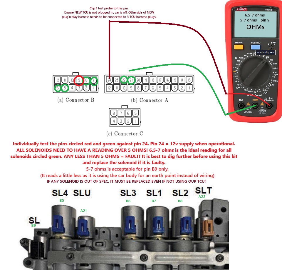
OTHER RECOMMENDED CHECKS:
A little bit of extra time here can give you vital information about your solenoid health! It is recommended you perform this check on all the solenoid wires at the NEW TCU controller to ensure your valve body will operate correctly. Even if you do not use this kit, this check can be very useful for diagnosis and general health information about your valve body.
Once satisfied with the wiring run, you can re-fit the covers, refit the connectors to the BOOSTEC TCU and refit the glove box and be ready for your first start. It is recommended you have the USB cable protruding over the glove box to the passenger seat area.
If you choose NOT TO have a check via. internet connection using your WINDOWS LAPTOP and support connected on the other end, you can drive the vehicle and check the operation only! It is absolutely NOT RECOMMENDED TO DRIVE THE VEHICLE BEYOND A SIMPLE CHECK up to 20kmh and no more than 2 minutes of engine running without performing any checks on the tuning software. Any driving here is done at your risk entirely, even if it is at slow speed! We recommend waiting for your booking before driving the vehicle at all. RISKY BEHAVIOR LIKE THIS IS NOT ENCOURAGED.
Minimum required checks if performing basic checks without support connected (Not recommended and entirely at your own risk):
-Does the shifter position display correctly?
Please start the car and shift between gears. You should have NO ERROR CODES on the dashboard.
Please shift through all gear positions (PRND + M). If you have the positions showing like factory on the dashboard, you can assume the unit is communicating with the vehicle.
if you do not have gear positions (And only have a line for the gear position), please contact support and do not continue to use the kit until support gives you assistance.
Does the diff lock activate and a relay is heard clicking on-off when engaging / disengaging?
If you have purchased and fitted the DIFF LOCK ANYTIME harness add-on, press the diff lock button to check if it is working correctly. You may need to roll the car in gear forward a few meters for the DIFF-LOCK to engage.
Turn off the diff lock once the test is completed (Again you may need to roll forward to allow it to turn off and lights disappear from the dash)
Does selecting the gears in DRIVE and REVERSE work correctly?
IF SOMETHING DOESN’T SEEM RIGHT, DO NOT CONTINUE AND CONTACT SUPPORT.
Shift into R, N, D and you should feel the gears engage without a massive thump.
Drive the vehicle slowly allowing a 1 to 2 gear change at around 18kmh.
Did it shift?
Flick over to MANUAL and is it showing 2nd gear on the dash?
The simple checks are now complete. It is recommended you perform your checks with support connected to the unit via a USB cable and laptop with remote connection. There is absolutely no warranty/cover/guarantees for anything without these checks being performed without support being connected to your car. (Warranty is limited to the supplied parts only once the checks are performed with support)
The most important part of the checks is to verify that the speed input signals from the gearbox (TISS and TOSS) are being correctly picked up by the BOOSTEC TCU. This can only be done by remote-login or by someone trained to use the software for the TCU. If they are not correctly picked up, the shifts will be trash and lock up/gear shifts will be confused. The possibility of this is now is very small, but it is recommended to be verified. YOU CANNOT DRIVE THE VEHICLE FURTHER IF IT DOES NOT PASS THE SHAFT SPEED SENSOR CHECKS, abort the tests, and do not operate the vehicle until you have contacted support and worked out a plan.
If this is all too much, please contact us for a recommendation for an installer in your area.
If for whatever reason you need to move wires or add wires to the connectors, the instructions below are for you.
To de-pin these, we use a Molex Minifit JR de-pinning tool. As a quick solution, we have found that the metal strip from a wiper blade can be folded over itself and be used to de-pin. (We can do this for you if you have an early model where this was not on the QC list at no cost). The access is from the front face of the connector.

How to use and features:
There has been over 600 hours of development time in producing this kit and software and we still don’t believe it is perfect! So please give us constructive feedback and we will happily address any requests, especially if custom tuning hours are included or purchased separately.
You should be able to drive completely normally in drive mode and you’ll notice significantly shorter shift times with some firmness increase. If you feel EXCESSIVE shift clunking or flaring, contact support.
Drivers wish: Whenever you mash the throttle in any gear, we have instated a progressive lock up clutch pulse modulation to reduce flaring. In the first release version there is a trigger setup based on the following: 3rd gear and up, 75% throttle and up, 2600 rpm and up = Progress to full lock up and disengage lock up for shifts. This is to protect the clutches and temperatures that can be encountered while in aggressive driving.
Manual mode: Manual mode disengages lock up in low load but re-engages if the driver wishes to give it hard time above 2600 rpm with the previously mentioned criteria. If you wish to engage lock up in manual mode use the CANCEL button on the cruise buttons.
When downshifting using the manual mode, you will notice that instead of a 2+ second delay for shifts to complete, most are completed in under 0.7 of a sec giving you near instant engine braking.
In the final software we have been instating a minimum speed for each gear. This will return the car to 2nd if you forget you are in manual and slowing down to a stop.
Multi-map: Multi-map is selected by HOLDING Cruise SPEED UP or CRUISE SPEED DOWN for .7 of a sec. You’ll have a yellow/red flash on the dashboard for when you are in TOW-MODE or red flashing on its own for NORMAL/SPORTS mode. You can change this on the fly. In tow mode, 6th gear access is also disabled in auto mode.
CRUISE SPEED UP SETS NORMAL MODE
CRUISE SPEED DOWN SETS TOWING MODE
This resets everytime the car is restarted and defaults to normal mode.
Diff-lock: The Diff lock button also now instantly will engage diff lock in any gear, any speed and any transfer case position. So please be aware of this. (Only if you purchased the full TCM suite) – We are considering extending a timer extension to avoid accidental touches.
Temperature warning modes: If you hear multiple beeps in series from the dash, this means a high temperature has been detected in the transmission fluid (Either in the valvebody circuit or in the TC circuit) – This has been implemented so you can give the fluid a chance to cool down. Engaging the forced lock up (holding down the cruise cancel button for 1 sec) will reduce the temperatures being generated and bring the temperature warning under the hysteresis threshold – ending the warning mode. IF YOU CONTINUE TO INCREASE THE FLUID TEMPERATURE, you will enter the final warning mode, which is the audio warning and a SOLID RED TRANSMISSION symbol on the dash. If you do not yield to this warning, you will be degrading the fluid and potentially damaging components in the transmission. If you repeatedly get into the warning modes, it is recommended that you look at increasing the cooling capacity of your trans fluid. The systems are not fool proof but at least you have effective warnings for the transmission as opposed to what the stock system does.
Manual mode: Gear selection must be sequential. Skip shifting has not been enabled.
Expert mode: To use the artificial lock up without limits at lower speeds, hold down the cruise-cancel button for 1 sec while driving. To deactivate, tap the cancel button again. There is some safety built into the system, but please be aware that if you shift into lower gears while this active, you will get a nasty clunk. It’s purpose is to use during off road single gear use to prevent over heating of the gearbox or to use engine braking while towing under 75 kmh. It was a heavily requested feature that’s not for everyone. Please note as stated at the top, there is possible way to have lock up in 1st gear. Use 2nd or higher where heating of the torque converter may climb rapidly.
To use manual gear cruise control: Setup your cruise as per normal driving. Then select manual with gear stick, cruise disables! Now tap the RES button on the steering to activate manual cruise, tap RES again to return to standard. The vehicle will function normally while in manual cruise, but you will notice the gear indication display has changed. The only reason you will want to goto standard is to have normal gear indication.
Clear limp mode/codes: An added feature was a clear code function like what a scan tool has. It’s an added feature with no specific purpose unless a strange event occurs with a tuning module or a damaged sensor etc (unrelated to the kit) To clear codes: repeatedly hit the cruise distance button 5 times within 5 seconds.
Low range tall gear select: When off road and in low range, you’ll notice only 1st, 2nd, 3rd are accessible in factory form, now you have all gears.
Engine braking mode: As you push the brake in further, you’ll encounter progressive downshifting and engine braking.
To activate engine braking in 1st gear, the engine speed needs to exceed the torque converter speed at least once for the braking clutch to engage. This can be done by blipping the throttle or by using the rev-match from 2nd to 1st when manually shifting from 1500rpm or higher in 2nd.
Future updates hit list:
If you would like to trial any BETA improvements to the kit, please contact support.
Some of these features we will be exploring are: Skip shifting, Trans-brake, Multi-mode shift scheduling (like low range), self-learning/adaption, integration with scan tools, trans-brake bump, paddle-shifter plug ins… As features are added, it is your responsibility to request updates to existing modules.
Currently there is no support for scan tool PID’s showing transmission information. Although this is being explored.
Disclaimer:
This kit is supplied AS-IS and implies no warranties or liability cover for any components or chattel when it is being used. It is up to the operator to decide if the kit is to be used, it is at their own risk. Any warranty implied is ONLY for the supplied parts (When new) with absolutely no warranty for any connected devices or the transmission itself. All use, misuse and handling is done at the risk of the operator.