(Please note, this is a very old video now, showing the original CAN HACKER (Discontinued) – Please read the ENTIRE document here to find out about your purchase!)
https://www.youtube.com/shorts/oublV5zlYhs
Minimum tools required for full install:
Small socket sets in the 6mm-12mm range can help with installation.
A 6mm, 10mm and 12mm socket are essential for firm installation.
Pry tools for trims can help, although not necessary.
You can get the kit going without tools and just your hands if absolutely neccessary.
***
An additional mounting plate has been included (Since Nov 24) to make installation easier! The heat sink bolts onto the plate and the plate is fitted onto the back of the TCM screws.

***
1. Remove the glove box, this is done by opening it by the handle, then by pulling the glove box towards the roof from the bottom hinge, then you remove the glove box on an angle out of the cavity.
2. Remove the KEY from the car, do not have it inside the car (Especially if its push button start)
3. Remove the airbag receiver insert plastic surround near the glove box – (approx size of 1/3 of A4 paper) and let it dangle (its on the left of the glovebox) It’s just in the way, it’s used for airbags with front kid seats. You can unplug the 2 pin connector if you wish (Don’t forget to re-connect it after!)

4. Now you can see the TCM with 3 cable looms (Pink yellow green), un clip the bottom cable loom from TCM and insert the supplied LOOM connections into the TCM bottom connector and TCM loom for the same connector.
5. Remove the top connector of TCM and insert the ADAPTER into the TCM and TCM loom (It has a shielded twin core black wire wire section) Next, carefully connect the bottom connector of the ADAPTER to the TCM. Make sure the connection is secure and the wires are properly aligned. The middle connector remains connected “as-is” it must remain connected to the silver box.
6. Ensure everything clicks in and there is no LOOSE WIRES or connectors! (Photo below to show you orientation) In addition to checking for loose wires and connectors, it is important to double-check the orientation of all components before finalizing the installation. This will help ensure that everything clicks in properly and functions as intended.

7. Run the long switch loom to the right side of glove box area behind the plastic supports of glove box.
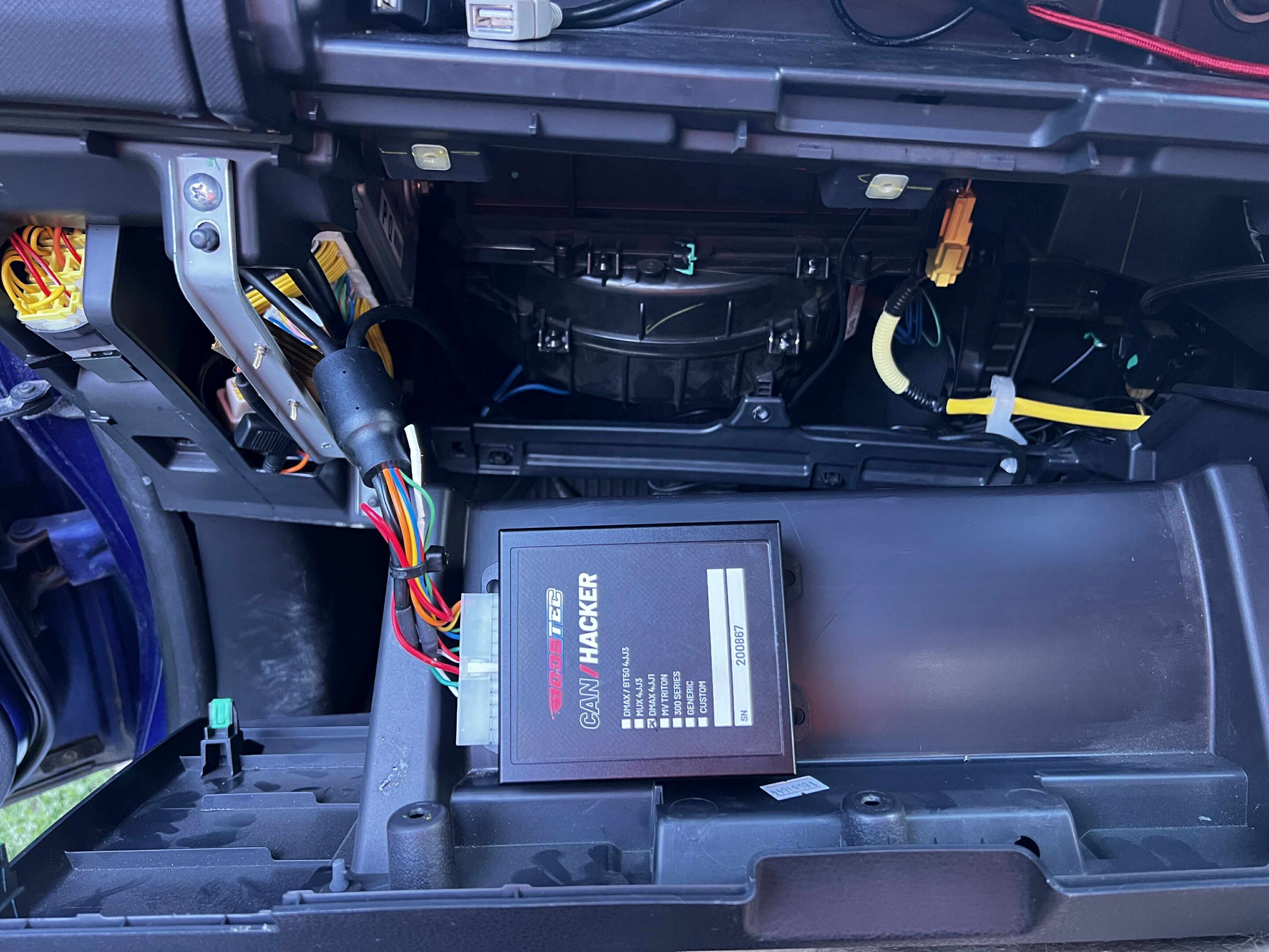
8. Plug the Boostec box into its 24 pin Minifit connector – Ensure the tab clicks down!, it can be mounted onto the provided plate, to do this, assemble the heat sink onto the plate, the control box onto the plate,
undo the 2 TCM screws (on the cars silver box) and push the plate as assembled into the cavity. Then you can do up the 2 screws for the TCM and everything fits in perfectly.
At this stage its a good idea to ensure all wires and connectors are snug! If you have a can-hacker 2.0, please check the 2 pin wires on both ends of the line pressure box are firmly inside the connectors. You can give them a quick tug test. (If loose please get in touch with us immediately)

9. Previous versions needed the heat sink to be mounted in this location (Now redundant, only for reference on older kits):

Please note this is only applicable to BASE model DMAX and BT50 and 4jj1 installations:
4JJ1 2016-2020 &
DMAX 2021-2025 “Base models”
On manually operated aircon models from 2021-2025, the supplied mounting bracket will not fit next to the TCU. You will need to make do with cable ties and limited use of the mounting plate.
The same applies for 4JJ1 installations, you will need to get crafty with cable ties. Please ensure you do not place the control box near the hot pipes or heat vent for the cabin.
Most 4JJ1 installers cut up the supplied stainless bracket to only allow the heat sink to be mounted onto the TCU bracket.
This is then followed by mounting the CAN HACKER on its own with cable ties or preferably in a location such as this (with velcro/double sided tape). Example 2018 4JJ1 shown below
10. Run the green plug wire to the TRANSMISSION GEAR SELECTOR AREA. Pop up the gear selector surrounds using anything that won’t damage the plastics, we found this can be lifted with fingers if you’re careful. A pry tool can be used to help. (It literally pops up from the rearward edge)
If you have a MUX with heated seats, your only option is to run the RECTANGULAR type switch to where the driver’s knee is. If you don’t have ANY available switch holes, you may need to activate the switch and hide it behind the dash. Its typically not accessed once its in the vehicle and tested.
11. Push out a blank for the button (from the not visible side, it has 2 tabs) and run the cable thru the bottom of the blank hole to poke out to the gear selector area.
12. Fit the button (from the driver visible side of the receptacle) and insert it into the hole, fit the green connector into the button. Push closed all the plastics and the button should sit flush.
13. Cable tie any cables you wish out of the way and re-fit all plastics around the GLOVE BOX area. Now you can start the car…
14. Everything should work as stock, no errors should be on dash. If you have errors, check your install with car OFF.
15. Push the transmission lock up kit button in and go for a drive!
Important notes on fitment!:
Ensure the LOCKING TAB is fully DOWN on the control box, don’t be like this guy complaining of “random errors on the dashboard” !!!

Ensure the ORANGE and GREY wires for the heat sink are pushed away from any sharp edges of metal, we are improving the heat shrink material in FEB / 26 around this area, but please just make sure it is not resting on the metal. This is one way a lock up solenoid can fail if this grounds out. (Not the end of the world, but we do want to see happy motoring from all users)
Note for Canhacker 2.0 owners:
Installation is the same, some bulkier parts are included but are unaffected during installation. Please note: The line pressure modifier has a switch! This switch should be in the down position (when reading the text on the small box). The switch is used as an “anti-learn” feature in the case the stock TCM starts to adapt to the higher line pressures. It can be activated for a few 100kms and this will force an un-learn. In practice, we haven’t seen a circumstance when this has been needed to be activated. The switch can be favorable to be left in the “up” position for some tuned vehicles where the torque translation data in the ECU has been modified. Either position will work.
If ordered, you may have received a “diff lock anytime” extension loom. This runs all the way from the TCU / Glove box via the 2 pin connector (In V3 kits, it is a 4 in connector! – Not in common kits), to the right hand side kick panel area. You need to locate the DIFF LOCK controller (approx 50cm from the floor of the car in the corner of where your RIGHT foot would normally be when driving) – You disconnect the white connector and fit the can hacker patch loom in between.
A short video here demonstrates how this is done:
After installation, the stock diff-lock button now will activate and de-activate the diff lock in any driving mode. Please use with caution! It is not designed to be used on bitumen or paved roads of any type.
There is absolutely no liability accepted by us for the fitment or use of the diff-lock anytime! If in doubt or the risks are too high for you, do not fit this section of the loom/
You may have also received / ordered a fuel tank calibrator with the package,
the installation guide is here:
https://boostec.com.au/fuel-level/
This short video demonstrates its installation area and usage:
How to use your lock up kit:
The push button arms the kit for automatic operation. Usually you never take it out of the on position. It will lock at 77 and unlock at 74, you don’t have to do anything in this setting, it’s done for you automatically. This mode is considered the safest way to use your lock up kit.
(The following will not work with 4jj1 models prior to 2020)
Expert mode: To use the artificial lock up without limits at lower speeds, hold down the cruise-cancel button for 1.5+ sec while driving. To deactivate, tap the cancel button again. There is some safety built into the system, but please be aware that if you shift into lower gears (2nd and 3rd especially) while this active, you will get a nasty clunk. It’s requested purpose is to use lock up during off road + SINGLE manual gear use to prevent over heating of the gearbox or to use engine braking while towing under 75 kmh. It was a heavily requested feature when we first released this kit and we also note that its use is not intended for everyone. Excessive use of expert mode (forced lock up mode) can lead to excessive wear in the gearbox. Its intended use is for situations where a steady speed and gear is to be held where automatic function is outside its safety range. Some safety is built into the system, however when using the “expert mode” you are in control without most safety features. Your discretion of its use is paramount and this is a clear reminder that there is no chattel warranty when using this kit in general.
If using this feature on the beach, your ideal conditions is to be in a manually-selected-gear prior to holding a steady RPM where you have ample torque reserve. For a standard car, this might be 4H – 2nd or 3rd @ 2600-3100 rpm or for tuned cars 4H-3rd @ 2300-3100 rpm. Its very vehicle/driver dependent. Choosing a too high of a gear on soft terrain is usually a mistake, you want torque and rpm reserve in most cases.
The kit isn’t going to save your transmission in every case of driving, so don’t rely on it to replace driver choices – The kit is designed PRIMARILY as a tarmac towing solution!
To use manual gear cruise control: Setup your cruise as per normal driving. Then select manual with gear stick, cruise disables! Now tap the RES button on the steering to activate manual cruise, tap RES again to return to standard. The vehicle will function normally while in manual cruise, but you will notice the gear indication display has changed. The only reason you will want to goto standard is to have normal gear indication.
Clear limp mode/codes: An added feature was a clear code function like what a scan tool has. It’s an added feature with no specific purpose unless a strange event occurs with a tuning module or a damaged sensor etc (unrelated to the kit) To clear codes: hold the cruise distance button for 5 seconds.
Low range tall gear select: When off road and in low range, you’ll notice only 1st, 2nd, 3rd are normally selectable. If you hit the cruise RES button, you’ll be allowed to select the taller gears aswell. It is recommended to never use the lock up kit in expert mode while in low range.
How do I know if the kit is working?
With the button pushed in (activated), when you reach over 77kmh – you should hear a relay click from behind the glove box and in most cases see the rpm drop slightly on the tachometer.
If you’re still not sure the kit is working, try accelerating say half throttle, from 75kmh and higher and repeatedly hit the lock up kit switch on-and-off, on-and-off. Everytime the kit is clicked on, you should feel the car lock in firm into gear and also see the rpm drop slightly, with the rpm rising and also a click when the kit disengages.
If this does not happen, we have one of 3 scenarios:
-A faulty button
-A faulty car converter/solenoid
-A faulty kit
If you DO NOT hear a click when the kit engages (at the relays) please check the button is pushed in as the first step!
Troubleshooting and tips and other information:
Having access to over 1400 vehicle’s for diagnostics, in shops or just from general interactions with customers there is a few common areas of concern we would like owners to cover. If you haven’t checked your fluid level in the transmission, it is imperative to do so! In factory systems it is rare to come across any low levels, but for those with additional TRANSMISSION COOLERS fitted, close to half (yes 50%) have low fluid. Critical low fluid is between 300-500ml below required (We find in about 25% of vehicles with additional coolers fitted). We always fit and recommend to set the fluid level when “cold” or about 20-30 degrees C. This may overfill slightly some vehicles, but the benefits negate any risk here. It is not un-common for air-locks to work their way out of the systems over time.
The risk of low fluid is not enough in the valve-body or pistons for actuation and localized heating can occur! Do it for your own peace-of-mind.
Fitted a cooler? Fitted a valve-body upgradE?
SET YOUR FLUID LEVEL COLD, IN PARK, AFTER CYCLING YOUR SHIFTER IN P R N D. 20-30 Deg C is what we do and have had ZERO issues. IT IS ALSO BEST PRACTICE TO DO THIS AGAIN AFTER AT LEAST 1 FULL DRIVE CYCLE.
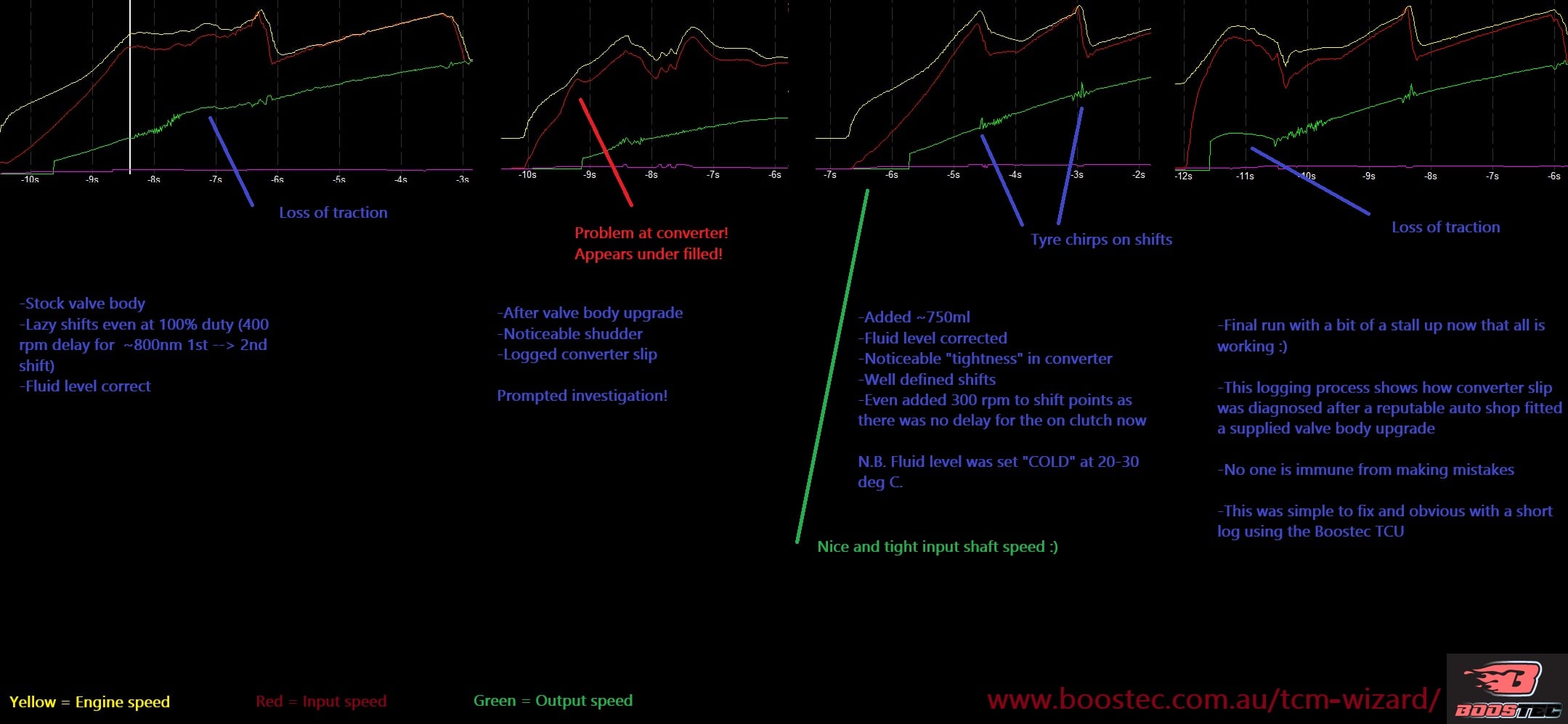
//Edit//
Again, we harper on about this a LOT! Our own company race car went to a reputable gearbox shop in Sydney and guess what, it was under filled! We had a modified valve-body put in and something was off. We logged the vehicle BEFORE then AFTER workshop visit and then AFTER we topped up the fluid with (drum roll) 750ml!!! The evidence is unequivocal. If you don’t want to risk your CONVERTER being low on fluid, or your VALVEBODY sitting high and dry (sucking in air) – A scenario that is entirely possible with where the pick up is positioned (Rear of box, making it susceptible to this issue in downhill positions). Solenoids all require to be lubricated and cooled.
Ignore this at your own peril, don’t believe us? Here is the results:
//Edit//
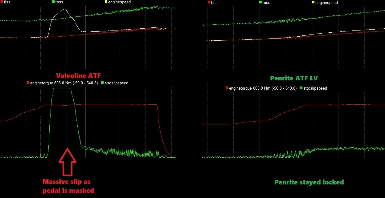
Also, here is what happens when you have THE WRONG fluid in your transmission!
Here is a list of ATF’s we have tested and which are also listed as being compatable.
- Penrite ATF LV (Full Syn) — explicitly lists Isuzu ATF WSI
- Idemitsu ATF Type-LV (OEM)
- Fuchs TITAN ATF 6400 (We personally haven’t tested this one, but have on good word it works well)
- Nulon Multi-Vehicle ATF / FS-ATF Premium — lists WSI (We personally haven’t tested this one)
- Liqui Moly Top Tec ATF 1800 — lists WSI (We personally haven’t tested this one)
This is what a transmission specialist put in (Valvoline) and check out the difference in the slip in 5th gear, rolling it on with more torque than anyone else reading this will make. So do not experiment with fluids, if you’re chasing down problems, start with the simple stuff!
*BEEPING SOUND SECTION*
IF you call on the phone asking about this, without having read this part, that’s a carton! 🙂 You can deliver the said carton to: Boostec Cartons, Locked bag 166, St. Peters, NSW, 2044.
(That’s a joke, but in all seriousness, this is a purchase option, a documented feature and it is there to save your butt when the factory transmission is in general getting hot! – There is no excuse for missing this information)
A 112 degree C temperature warning alarm has been added to the new kits since 10-NOV-2025, you will get audio beeping from the dash board if you ever get your gearbox fluid hot. It will only operate while it is overheated. It is there for all users to either to force your eyes onto your SCAN GAUGE TEMPERATURE display or to give you heads up that you are using your vehicle in “extreme conditions” (Not my words, Isuzu’s words). This will usually come on from driving in a hilly area while towing while the outside temperatures are hot and you don’t have a ATF cooler installed. Its also used as a warning to let you know you have excessive slip in the gearbox. If you ignore it, you can experience a major gearbox fault. (We also have the option for 125 deg C if you monitor your own temps and only want a critical temp warning)
N.B. The factory system lets you get to the point of no-return, the idea of this warning is to give you time to react – typically selecting a single gear (where say an engine rpm of 1800-2400 is available) and forcing expert mode on to reduce slip – If slip continues while locked, please contact us for advice – You can read below for more trouble shooting tips.
If you’ve previously overheated your gearbox, please be aware you may have damaged it. Its always a good idea to have fresh fluid in the box if you’ve degraded it. Seals can harden, plates can overheat and clutch surfaces could have worn down. This kit is not a band-aid for damaged/degraded boxes, the idea is to prevent over heating events by using the kit in the first place.
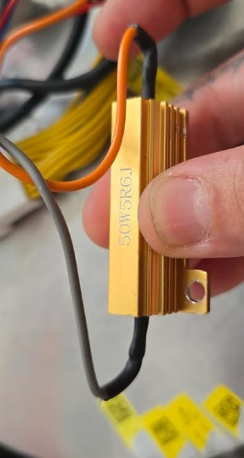
If you have the button for lock up pushed in and you don’t hear the relays or feel the lock up engaging (at 77kmh or above in auto mode), please check the fuses first and if you have a spare alternate shape button (supplied) you can also temporarily use it to test if the other button is faulty. If you still don’t hear the click and EXPERT mode also doesn’t engage, check the fuses and perform an OHMS test across the terminals as shown below.
If while using this kit, you find that when fully locked up – You can still manage to get slip and/or temperatures increase while the lock up clutch should be fully applied – Then you will have to inspect the fluid and/or replace the torque converter in the worst case. The kit will not solve a worn-down surface. Please discontinue using lock up until diagnosed and perform an OHMS test. To help with diagnosing cars with slip, the following test can be performed:
A recommended test for all vehicles is to test the resistance for the lock up solenoid before completing the fit-up (before the first drive) or during trouble shooting.
If you connect the complete kit and disconnect the BOTTOM connector from the TCU only, find the blue and red wires and test the resistance across those terminals. The resistance MUST be 5-7 ohms to be considered normal and healthy for the lock up solenoid. Any less and its on its way out, less than 4 ohms = replace! Luckily it is easy to access on an exposed valve body. 5-6 OHMS has been the factory test range, but we find that when testing through the factory harness, this resistance is slightly higher (which is acceptable!)
As the vehicles rely on this solenoid to control the slip of the torque converter, it is paramount to ensure it is working correctly if it is ever suspected to be faulty. As these vehicles age, we find these are one of the first points of failure on a standard gearbox without our kit fitted.
The wires in question are shown here:
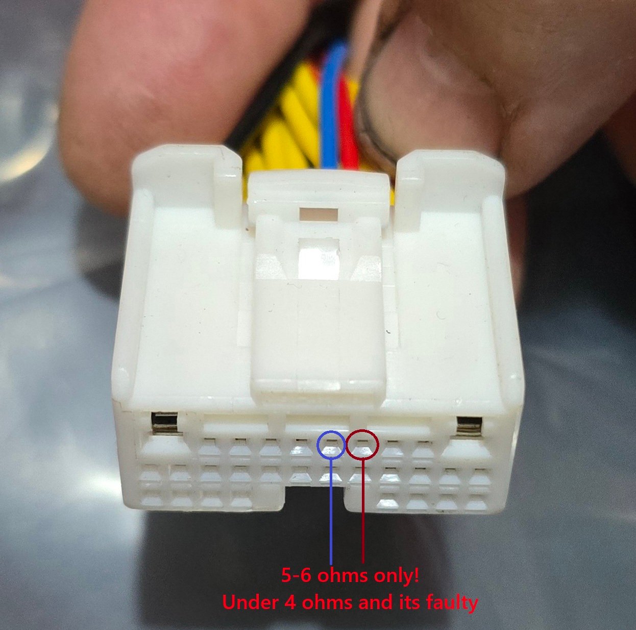
We see a variety of cars in different states and these are usually perfectly fine. But if you’re using this kit to try fix a slipping box, I’d highly recommend this test.
If you ever pop a fuse on the kit (10 amp), I can almost bet the reason is a faulty lock up solenoid inside the transmission valve body and this test will reveal that. If you don’t have a multimeter and you’ve popped a lock up fuse, remove the kit and start the car as if its standard. If you scan the vehicle for errors, you may find a range/performance code for the lock up solenoid, this is not a good sign to continue driving.
We’ve put a lot of effort into making these kits fool-proof and the fuse is there for this reason on the lock up circuit.
We have updated the firmware and display on the kits over the years. If you wish to have the latest firmware placed onto your kit, please contact us. The operation of the lock up remains unchanged since this kit was released in Nov 23. The changes are for the following: flickering lights for the trans have been used to show when the kit is entering lock up/expert mode, this has been removed in current kits and only a warning light pops up for “expert mode”. Diff lock anytime has been modified in its handling and a speed limit for lock up has been set to 74kmh. In factory form it is ~30 kmh. If you wish to have a lower or different limit placed, please get in touch. It is your responsibility of how this kit is used, if you wish to have a lower or higher limit, we can do this for you. Warning sounds for temperature and scenario’s to help you diagnose some issues that require your attention while driving have also been added in late 2025.
Specific to Can Hacker 2.0:
If you notice on a Can-hacker 2.0 that entering the P R N D gears there is any sharp firmness or clunk, it has been found that the 2 wires on the line pressure box the wires may have been ejected while wrestling the kit’s wiring into position. There also was a batch of wiring kits where the red and green wires have not clicked into place. Please check these wires are home (perform a light tug test) in their connectors and no wires are exposed (silver terminals aren’t flopping in the wind – all wires are terminated in the connectors). The vehicle defaults to full line pressure if line pressure control is disabled. We QC every loom, but as the complexity grows of the kits, its possible to miss a wire crimp is not fully home. Please tug-test the loom wiring at the plugs to ensure its robust – Especially on the line pressure control box ends.
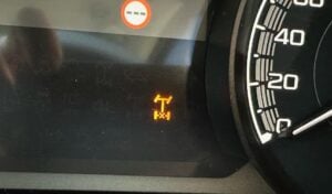
If you see this symbol after a CAN HACKER 2.0 install on key-on, the loom is not complete between the canhacker and the difflock controller. Please check all connections are clicked in, especially the 2 pin connector between the canhacker and the diff lock controller.
If you have issues with some cheaper scan tools connecting to the car, try connecting the OBD scan tool while the car is running or when it is off (try one or the other, yes its that silly). Unfortunately some cheaper scan tools don’t follow industry standards in how they communicate with the cars and attempt to hi-jack certain addresses by making themselves the highest priority part on the bus.
If you have come off the highway and noticed harsh down shifts, it is possible the “expert mode” may still be engaged. Tap cancel on the steering wheel if you are unsure if it is still active.
A majority of the logic components are rated inside the CANHACKER box are in the <90 deg C range for operation on our circuit board inside the cabin. We have found that unusual installations that attach to heater pipes at the air con mixer can run quite hot. For these unusual installations, please be mindful of temperature. If you are using the installation metal bracket, you should never have to worry about this. We have had a few units exchanged over the years where some additional cooling was needed to be installed. All current full aluminium can-hacker boxes have a heat transfer pad installed and its connected to the outer shell from the internal PCB. A full failure of the box (where it shuts down due to heat) results in a limp home mode, which allows R, 1st, 4th gears @ full line pressure and you will have a xmas tree light display on the dash. If you ever experience this, please get in touch. I’ve had 1 reported incident where during a heat wave and car was left in the sun, the inside temperature of the car was excessive and did not allow the box to start up until the vehicle was cooled.
I’m not a fan of what-if’s but its best that you are aware of what we have dealt with when over 1000 units have been sold.
Additional T&C’s and returns policy can be found here: