
Fuel level correction fitting instructions for: ISUZU D-MAX / MUX 2021+, MAZDA BT-50 2021+
FACEBOOK DISCUSSION GROUP LINK
(Generic application is also applicable for most Japanese style fuel level sensors)

Video link of installation overview:
YOUTUBE VIDEO FOR CONFIGURATION IN DETAIL:
________________________________________________________
Please be advised that while all necessary precautions have been taken, we cannot accept any responsibility for the installation process. It is at your own discretion to proceed with the installation, and we strongly recommend that you carefully read the warning label provided with the kit (if supplied). We do not provide any implied warranty for the installation or use of the kit.
Installation guide
Required tools:
The following tools are the minimum requirement for use, except in cases where stubborn plugs or the removal of the battery terminal under the bonnet is necessary. It may also be advisable to utilize cable ties in certain installations. We recommend the use of a 10mm socket+ratchet, side snips for wires, small plyers, cable ties, and a trim removal tool for optimal results.
Note:
Prior to commencing any work, it is recommended that all power sources to the vehicle, including batteries, be disconnected.
Instructions:
- Take note of your fuel level position (ideally you’ve driven ~100km from full or have just encountered the LOW-FUEL warning lamp – ideally take a photo) and then disconnect the battery from the vehicle under the bonnet before commencing any electrical work.

- Locate the passenger side kick panel, remove the plastic blind nut and remove the kick panel.

- Remove the 10mm bolt holding the white harness gang cover

- Rotate the white lever while pushing in the front of the locking tab, it rotates all the way up and you can remove the white wire cover by squeezing the bottom of the cover side-to-side or by using screw drivers to pry the locking tabs.


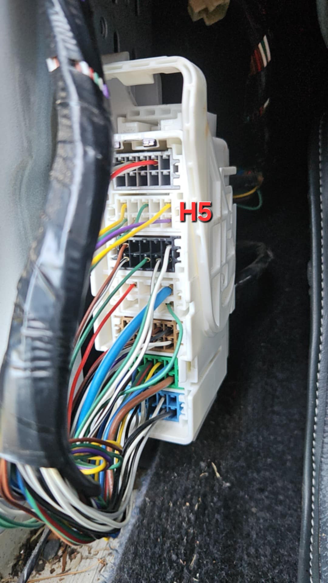
- Find the 4th plug down from the top (It has been consistently a BLACK color)


- On the top row of the black plug, you’ll see one of 2 styles of wiring coloring..


- Early Dmax / BASE MODEL /Key start models 2021-2022: FROM RIGHT-to-LEFT: BLUE, YELLOW, GREEN on the top row of the black plug. (We are interested in the YELLOW and GREEN wires)
- Late model: 2022+ Push button start models: FROM RIGHT-to-LEFT: BLUE, YELLOW, PINK on the top row of the black plug. (We are interested in the YELLOW and PINK wires)

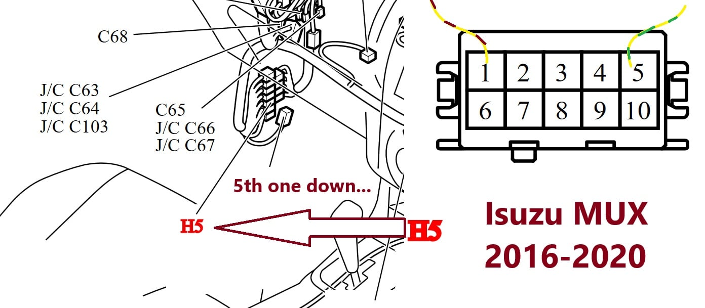
NOTES for 2016-2020 model DMAX – MUX:
For 2016-2020 models with the 4jj1 engine, the only difference is the wires used.
We still use CONNECTOR 4 (from the top), but the pins are 1 and 5 (Which are both colored yellow)
It is recommended you do mark the wires with a black marker to know which are which.
Please use this as your connections for 4jj1 2016-2020:

2016-2020 4JJ1 MUX models:
- With about 50-80mm of wire exposed, please snip the wires.

- Place the supplied quick connectors onto the exposed wire pairs (Disconnect them from the supplied kit ends at the black joins) – pull them away from the supplied kit ends
- You flip up the clear sections of the quick connectors, feed the YELLOW/GREEN or YELLOW/PINK wire pairs into the holes of the clear plastic, push the clear down slightly, ensure the wires are lined up central on the metal receiver and nearly pushed in as far as they go: Now click the clear plastic down and the wires will remain locked inside – I usually lightly squeeze the quick connectors with some pliers to ensure they are locked and the side tabs of the clears are fully over the black section.

- Repeat the same for the other side of the pairs, ideally ensuring that if the black connectors we’re to plug into each other, that the wire pairs are running the same color thru the connectors.

- You can click the 2 connectors together and it will be like OEM just to test this. But we would like them to be disconnected from each other, instead:
- Connect each end of the quick connectors into the fuel corrector device. There is no polarity issues, but if unsure, follow the photos.
- Now ensure the connections are good, a light tug on the wires will tell you if they are home properly. Correct as needed.
- Put the white wire cover back in place, fitting the top locking tab first and pushing hard at the bottom until it clicks in both sides (be careful to include all wires to the inside of the cover)
- Put the 2 gang connectors together and rotate the lever down to lock the harness back in place.

- For testing purposes I would suggest you do not fully re-fit the 10mm bolt and kick panel cover, save that for when you are satisfied with the install and tested the kit fully.
- Re-connect the battery to the car and you can set the HI setting 1 = ON, ALL OTHER SWITCHES = OFF.

- Turn the ignition on and confirm you have fuel level as prior to install.
- Now with IGN on, flick all settings to OFF and you should have no fuel showing on the dash.
- If you only want to alter your HIGH reading then It is recommended you flick the HI switch 2 = ON. If you’ve consumed 10-15% from full, it should now drop by 1 bar. You could also try ALL OFF and HI 3 = ON for an aggressive movement from the FULL mark (Say 5 ltrs consumed = 1 bar from FULL). Ideally, when setting both HIGH and LOW levels however, it is recommend to start with setting THE LOW and having the HIGH on setting 1.

- The difficult part is setting the LOW level. The best way to do this is to run your tank down with all LO = OFF until the warning lamp comes on for LOW FUEL. When this occurs, you would ideally have your HI setting sorted (it will change slightly with some aggressive LO settings) – And you want to set this again with the IGN on and flick all the toggles to = OFF. Then toggle on LO 2 = ON and your HI setting as previous (Recommended starting point is: HI 3 = ON, LO 2 = OFF).
- The reason for flicking all the TOGGLES = OFF before putting in a new setting, is it simulates you filling your fuel tank from empty to a NEW reading without the dashboard smoothing out the changes it is receiving. The dash effectively averages out changes so your fuel level doesn’t bounce.
- Once you are satisfied with your LOW fuel setting and HIGH fuel setting, you may fit the fuel corrector into the white cover or cable tie it to existing wires.
- With key off, re-fit the connector gang back to the body with the 10mm bolt, ensuring the bottom locating tab is in on the sheet metal before screwing in the bolt.
- Ensure no wires are loose, re-fit the kick panel cover and go fill up the car again.
- It is advisable that you monitor your fuel level vs. kms for a tank or 2 of fuel to get used to when the LOW FUEL level comes on. It is always possible to run out of fuel in the tank with new settings if you are not mindful of the new settings.
Some advice on settings:
You can use a combination of HI and LO toggles to get the desired effect, you may find that for instance: HI 2+4 = ON and LO 3 = ON may suit you more than other settings. The good news is, you can’t destroy your fuel sender using this kit and miss-managing the toggles. The worst that can happen is your combination reads EMPTY or TOO LOW when there is still fuel present.
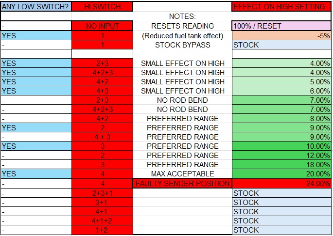
Quick notes on positions (please remember to turn ALL dip switches off with the IGN on, before setting a new setting – This resets the averaging of the fuel level instantly!)
131 LTR tanks seem to like the 3 HI, 2 LO setting (9% effect up top, 5% effect on low)
145 LTR tanks seem to like the 3 HI, 3 LO setting (10% effect up top, 8% effect on low)
All HI OFF = NO FUEL TANK READING (reset)
HI positions effects depend on combination used:
I’d appreciate feedback on which settings you are using for which style of fuel tank. Also if you have a dead empty tank and you know that fuel is present, it is possible a wire has come loose. Be sure to tug on the wires after install to ensure none just pull out easily.
To by-pass the kit completely, just remove the kit from the quick connections, and plug the car’s quick connectors into each other.
-Chris
The operation of this equipment should only be performed when deemed necessary. Any operation of the equipment is at the sole risk of the user, and ODS assumes no responsibility for any direct or chattel warranties or liabilities. The user assumes full responsibility for any use or installation of this equipment and proceed at their own risk.
Thank you for supporting Boostec.